
Introduction
Measuring torque is a very important aspect of the electric machine industry. Torque ripple is periodic disturbances in torque, and it results in noise vibration. The chain from battery to vibration and how torque is affected throughout this is very important when identifying the source of this noise vibration.
Noise vibration is an important factor to control in machines and so analyzing torque accurately is essential in the work of electrification engineers. HBK provides industry-leading testing and measurement equipment ideal for evaluating torque ripple and analyzing the complexities surrounding it.
What is Torque Ripple?
Torque Ripple is Periodic Disturbances in Torque
Figure 1: Effect of averaging and filtering on torque information. Image Credit: HBM
Torque ripple is a periodic disturbance in torque, and so it is not a static value. Torque is often seen as an average value, such as that which is shown by the black line in the top graph. However, torque has a frequency component and an amplitude component. It is an AC imposed over DC value, caused by excitation and construction.
Torque is often misunderstood because it is looked at when heavily filtered. The bottom graph shows a load step for a torque signal. But by looking at the instantaneous torque in red, it is clear that the torque has frequency and amplitude.
Even when approaching the steadier state, the torque ripple has frequency and amplitude. If this signal is heavily filtered, which we see in the black, all of these frequency and amplitude details are missed, as well as dynamics. Even a little filtering can distort the torque ripple signal and cause missed information.
Where Does Torque Ripple Come From?
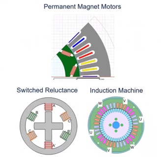
Figure 2: Different machine types have different types of torque ripple. Image Credit: HBM
Permanent Magnet
Many of those measuring torque ripple work in electrification markets, where it is predominantly permanent magnet (PM) machines are being used. In a PM machine, torque ripple is the magnet interaction with the stator slots. Figure 1 shows an Internal Permanent Magnet (IPM) machine with the magnets in brown and the iron stator slots in gray.
As each magnet passes by the tooth, it wants to stick to the tooth and the magnet pulls towards that iron. If someone was to go up to the shaft of a machine and twist it, there would be a ba bum, ba bum sound. This sound is the cogging torque or that stator interaction. These magnets cannot be turned off. The magnet strength of control techniques can be reduced, but there is still going to be that sound. That is what the cogging torque or torque ripple is.
Switched Reluctance
Torque ripple in also seen in switch reluctance machines. If one of these coil magnets is turned, there is a very strong whip of the rotor over to the excitation. That pulse of the magnet creates a pulse of torque.
Induction Machine
In an induction machine, even though current is being induced into the rotor bars, there is no permanent magnet, though there is still a magnetic field that is interacting with the stator slots. From a construction perspective, torque ripple is a magnet on the rotor wanting to stick to the teeth on the stator, and that is in a static environment or while it is spinning.
Where Does Torque Ripple Come From?
AC Excitation
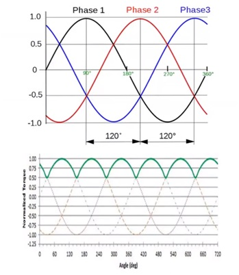
Figure 3: Three-phase excitation and resulting torque output. Image Credit: HBM
Torque ripple also comes from AC excitation. By looking at the purest excitation of an electric machine, there are three phases. Torque is added regularly, handing over from one phase to another.
Looking at the amplitude of the current signature, the torque is going to follow the peaks of the current. There is a torque ripple that is two times the number of phases, times the excitation frequency. There is a construction ripple, as well as a slower ripple that is coming from the actual excitation of the machine.
If the number of phases is increased, the torque ripple is decreasing but increasing in frequency. Different winding methods can be used to spread out the torque ripple and flatten it, resulting in a less drastic ripple.
There is going to be this ripple due to excitation. Different control techniques and switching patterns can influence the torque, for example a six step technique. If an AC frequency or a current ripple is put into this excitation, there is going to be a ripple translated to torque value. with an AC on top of it. That excitation, or switching frequency, is going to be seen in the torque signature.
Frequency and amplitude are proportionate to the number of phases and the rotational speed, taking into account any control techniques going on.
Torque Ripple from PM Motors
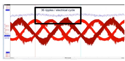
Figure 4: Three-phase motor excitation in red and resultant torque ripple in blue. Image Credit: HBM
Using a speed test it is easy to see how switching patterns and control techniques affect torque ripple. Figure 4 shows a very slow speed test, where there are three-phase currents in red. This test was running relatively slow, at around 10 to 15 RPM. However, it makes a good torque ripple example.
Looking at our torque in blue, you can see that there is frequency and amplitude in the signal. If this signal is broken down and the number of slots inspected, you can see that there are 36 ripples per electrical cycle. In terms of the construction of the machine, it is a V-shaped IPM.
The ripple is from the magnets interacting with the stator slots. There is an AC high-frequency content of 36 ripples per electrical cycle. For this machine, this would have resulted in 36 times two ripples per rotation. As speed is increased, frequency increases too.
Excitation does have some effect on this machine too because there is a slow speed ripple that is as a result of the excitation. There is a slow frequency ripple from the excitation and a high-frequency ripple from magnets interacting with the stator slots.
The point to take from this is that ripple is a function of construction and the ripple frequency, or the ripples per rotation, is a function of speed. As speed increases, the frequency of that ripple increases. Ripple is proportional to frequency.
Why is Torque Ripple Important?
Torque ripple is going to result in noise, vibration and fatigue. This comes with issues.
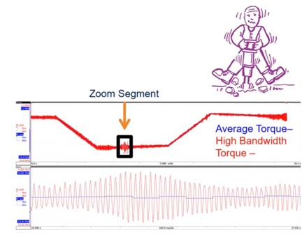
Figure 5: Instantaneous and averaged torque from the output of a gearbox. Image Credit: HBM
Figure 5 shows a long-term test where instantaneous torque is in red and average torque is in blue. There is an area of high amplitude, shown in the enlarged section at the bottom. This section has a lot of torque ripple and clearly has both frequency and amplitude within the signal.
This frequency and amplitude are going into a gearbox and this measurement is at the output of the gearbox. Torque ripple results in vibrations – the gearbox is experiencing gear chatter where it is bouncing back and forth. This will affect the lifetime and durability of the gearbox.
Torque ripple can excite structures. Everything that causes rotational torque has a tangential component going outward. It also has shaft resonances. This outward force can excite structures, causing vibrations. This resonant vibration can go into a gearbox and create noise and vibration.
The torque ripple has implications down the line, not just in the machine, but in the gearbox, the transmission, and the axle it is connected to. As speed increases, the frequency of the ripple increases. Ripple frequency is proportional to rotor construction and electrical frequency.
Control technique is also important within this In a six step control technique, another frequency is created – a higher frequency of that ripple.
Motors spin at a very high speed, much higher than typical engine speeds.
Why Motors Care About Torque So Much
The importance of motors and torque comes down to efficiency. How you measure torque affects the efficiency equation.
A traditional engine is 30 to 40% efficient. A 3% error gives you 39% efficiency instead of 36. This statement makes sense. On the other hand, in the electric motor, where efficiency is 85-98%, a 3% error potentially gives us 101% efficiency. This is impossible.
Torque frequencies need to be identified and captured in the exact same time period that electrical measurements are taken. This time alignment is essential in order to avoid small errors.
This applies to catching the ripple in the right time period. If in a high-speed machine, say 20 000 RPM, and measurements are off by a quarter Newton meter, that is half a percent of efficiency, which is a huge inaccuracy. To avoid this, users need to know what their zero is, what their frequency is, and what time period they are measuring on. All this needs to be perfectly aligned to their electrical signals, in order to get a good efficiency value.
User Experience
User experience is another element of torque ripple, as sometimes you can feel torque ripple. For example, in an electric car the sound of the torque ripple can lead to a negative driving experience. In order to overcome this, the sound needs to be sourced.
However, sometimes you want to feel torque ripple. For example, brushless DC drills do not necessarily need a clutch, and so it is not necessary to have something that stops you when you hit too much torque. User experience dictates that when a screw can no longer be driven, something needs to be felt or heard to indicate this. Hence, torque ripples can be designed to enable that drill clutch to be heard or felt.
Elsewhere, vibration can be hazardous, as is the case in electric aircraft. Take the X57, the NASA experimental aircraft, which has seven motors per wing. These have resonant modes that overlap with one another. Vibration could cause the wing to actually flap, which would be detrimental to its flight. It is important to avoid resonant modes from vibration that could be torsionally caused.
Measuring Torque Ripple
Accuracy, Bandwidth and Time Alignment for Transients
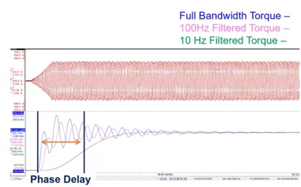
Figure 6: Top – three-phase excitation for an electric machine with a load step. Bottom – cyclical torque with different filter rates. Image Credit: HBM
It is important to have a full bandwidth for the signal. In this example, three-phase current is in red with torques in blue. There is full bandwidth torque, filtered torque and a heavily filtered torque. When applying the load step, there is a torque response that lines up very closely with the current response. This is the control of the machine.
A filtered version loses amplitude information and has a phase delay. This phase delay can affect how control can be tuned. If the pink line is obtained, but what is actually happening is the blue line, the user is going to be inaccurately tuning their machine.
Without filtering, it is clearer to see time alignment which is necessary for control calibration and understanding torque ripple. The frequency information in the unfiltered torque ripple provides fatigue information. When looking at efficiency, it is important to be able to see in detail exactly how many ripples have occurred for a given number of cycles.
Having this wide frequency torque also helps to test more quickly. Using filters means waiting for them to even out, and so the test takes more time, the machine is developed less quickly, and it is slower in getting to market.
Motor Analyzer Equipment
The HBM eDrive solution, the motor analyzer, is a useful tool that can measure voltages, currents, torques, speeds and vibrations, all in one place with a very wide bandwidth. It allows a complete understanding of not only what our torque ripple is, but what is causing it.
The tool is accurate and measures dynamic power, allowing measurement of power in load shifts. It is also expandable, meaning that higher phase count machines and multiple torques and speeds of up to very high numbers can be brought in.
All the data is recorded for review, enabling post-process analysis and a thorough understanding of the machine. There is a very high sample rate, which is very relevant for torque ripple measurement because you need to measure the torque at a high rate to get frequency information out. The machine can then perfectly time-align mechanical and electrical signals, allowing an understanding of not only the content of the torque ripple but where the torque ripple has come from.
HBM makes world-class, accurate torque cells of up to 0.02% accuracy with a six-kilohertz bandwidth. High accuracy allows you to see and trust very small disturbances in torque.
The cells output to a frequency signal rather than an analog signal. This is an advantage because whilst analog signals are very noise prone in a PWM environment, a frequency signal is almost noise immune. HBM also make accelerometers for customers who need to go into the high-frequency range.
In order to do torque ripple analysis, a high bandwidth torque sensor needs to be combined with high rate acquisition equipment. The eDrive power analyzer measures the torque sensor at its full bandwidth in order to fully visualize and understand that torque ripple. The acquisition system also correlates to other signals of interest – vibration and electrical signals. This can help if frequencies are going beyond the six kilo Hertz bandwidth.

This information has been sourced, reviewed and adapted from materials provided by Hottinger Baldwin Messtechnik GmbH (HBM).
For more information on this source, please visit Hottinger Baldwin Messtechnik GmbH (HBM).