
Measuring Torque Ripple
Equipment Needed
Some essential equipment is needed to effectively measure torque ripple. A torque sensor with really high accuracy and bandwidth is required, and noise immune torque communication is equally as important. Analog signals are extremely prone to noise in a Pulse-Width Modulation ( PWM) environment and so, if you have a ten volt signal, you are very likely to pick up inverter switching noise which can distort signals, especially if you are looking at torque ripple due to inverter switching.
HBM’s torque cells use a frequency output and frequency modulation. They output a square wave at a given frequency, and modulate plus and minus frequency based on torque. This makes them highly noise immune on the sensor side.
On the data acquisition side, you need a system that is going to record and translate that noise immune frequency output at a sufficient bandwidth. If you are not acquiring the signal and conditioning it correctly, you are going to lose all the bandwidth information that is there and available to you.
Furthermore, you want an acquisition system that is going to correlate that high bandwidth torque to electrical signals such as voltage or current, power signals, or other mechanical signals such as position, vibration, and displacement.
To be highly effective, engineers need two things: a high-end acquisition system with high-end torque sensors; and the knowledge of how to combine them for detailed analysis.
Accuracy, Bandwidth and Time Alignment for Efficiency
Accuracy, bandwidth, and time alignment are key aspects of a larger issue: system efficiency.
Take an internal combustion engine that is 30% to 40% efficient. A 3% error gives you 39% efficiency instead of 36%. This is great. When looking at electric machines that have much higher efficiencies, range is significantly more important because of the battery life. You have a motor efficiency of 85% to 98%. A 3% error here gives 101% instead of 98%, but this is impossible.
Torque ripple fits into this context because high accuracy torque accounts for really small disturbances in the average. To truly understand this, look at an equation for a somewhat high-speed machine:
80 kW @ 20k RPM → 2093 Rad/sec x 38.22 Nm → .25 Nm offset is 500 W →.625%
This example comes out with 0.5% inefficiency. The torque is an important measurement that must be obtained precisely and accurately, especially at higher speeds.
The bandwidth for our signal also needs to be time-aligned in phase with voltages and currents because, for efficiency, an average of torque and speed over time is taken and divided by an average of voltage and current over time.
Furthermore, time alignment is needed so that one of these high peaks is not added into an efficiency measurement, because having half a ripple instead of a full ripple could make a difference. Filtering this out would cause your test to be slower, and you would lose some of that bandwidth and phase information. There is real value in accounting for accuracy and bandwidth in your efficiency measurements.
Accuracy, Bandwidth and Time Alignment for Transients
For transients, this high bandwidth torque and torque ripple measurement also matters. This is more important for people carrying out calibration.
Figure 1. Top – three phase excitation for an electric machine with a load step. Bottom – cyclical torque with different filter rates. Image Credit: Hottinger Baldwin Messtechnik GmbH (HBM)
Figure 1 shows an example of a machine spinning at 7,500 RPM and having a load step applied from 0 to 150Nm. It looks at three different scenarios: full bandwidth torque, 100 hertz filtered torque, and 10 hertz filtered torque.
With the full bandwidth torque in blue, frequency amplitude of response time can be seen. For the 100 hertz filtered version, amplitude information is lost, and there is a phase delay. This tells us is that there is a delay between torque application and torque response. This phase delay can throw calibration.
To understand torque ripple in depth, phase information needs to be correct. It is essential to know what your filter constants are, as phase delay can come from filters in torque cells.
HBM’s torque sensors have digital filters in them that you can adjust. It is important to know how that digital filter is set, because highly filtered data is going to lose phase and amplitude information in transients. Time alignment is necessary for control calibration to further look into torque details.
The phase delay amplitude overshoot is a common way that people can harm their torque sensors, so it is important to be aware of what your dyno is going to do as far as torque transients.
Torque Ripple Examples
Torque Ripple from PM Motors
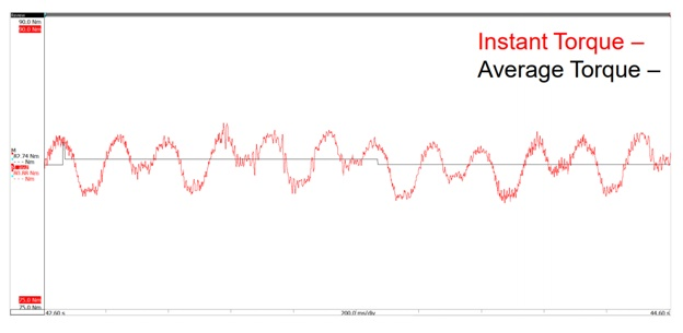
Figure 2. Steady state slow speed torque ripple. Image Credit: Hottinger Baldwin Messtechnik GmbH (HBM)
Figure 2 shows an example of a torque ripple from a permanent magnet (PM) motor. As previously discussed, this torque ripple requires accuracy to trust the amplitude and bandwidth to see the frequency content. By looking at this signal, magnet strength under different loading conditions can be characterized.
The torque ripple signal in the red shows a cyclical nature. Rotor structure can be identified from the torque response – here it can be determined that there is a V-shaped interior permanent magnet in the rotor (IPM) and the torque signature shows that the magnet is interacting with those stator slots at a relatively slow speed.
This is important for understanding the cogging torque, or the torque ripple at different loadings. In this test there is an 80 newton meter average, plus or minus two newton meter. Torque ripple was measured at different loadings. This test was done at 100 RPM, but you can do it at significantly higher speeds with a good bandwidth torque sensor. It is ideal for characterizing that PM torque ripple, and identifying it as an actual signal and not noise.
Torque Ripple from PM Motors – Control Change
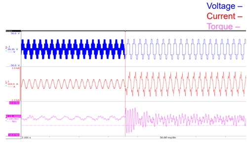
Figure 3. Top – voltage for a PWM to 6 step control change. Middle – current for a PWM to 6 step control change. Bottom – torque for a PWM to 6 step control change. Image Credit: Hottinger Baldwin Messtechnik GmbH (HBM)
Figure 3 shows an example of a control change in a machine. Control change is a really good opportunity to look at a transient torque, to compare one torque state to another and to begin understanding frequency domain.
On the left-hand side, there is a pulse wave modulation (PWM) creating a sine type excitation, with 13.5 kilohertz switching frequency. The result is a nice sinusoid, and the torque ripple shows little disturbance in torque. This little disturbance in torque is the torque ripple. The bigger disturbance is the dyno not holding speed very well and the magnets interacting with the slots.
Ripple frequency increases with control change. On the right hand side, the control technique changes and there is a six step switching at 600 hertz. There is a big change in that inverter switching frequency, which effects ripple frequency. There are gigantic torque swings in the transient, which are negative torque pulsations. This is a very heavy torque signature.
To understand what this means, it is important to look at the frequency domain.
Voltage, Current and Torque Frequency Content
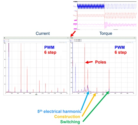
Figure 4. Frequency spectrum comparing current and torque during PWM and 6 step operation. Image Credit: Hottinger Baldwin Messtechnik GmbH (HBM)
Moving into the frequency domain, an FFT of the signals from figure 3 can be taken, shown in figure 4. The 13.5 kilohertz PWM is in blue, and the six step is in red. Fundamental and rotational current and torque or similar for both.
In the blue PWM signal there is almost no harmonic content in the current. In the six step, there is significantly more current harmonic content, with a really big fifth harmonic and a really big seventh harmonic.
Looking at torque, the fundamental is at 50 hertz, the pole ratio. Torque has significantly more harmonic content during the 6 step. There is a fourth harmonic that is likely due to the poles in that tooth interaction and a big fifth harmonic. There is also a 600 hertz torque disturbance, which can be tied directly to that switching frequency.
This torque signature has a lot of good content for these types of tests. By correlating these things and then bringing in vibration, an understanding of the whole system in one place can be achieved.
Comparing Electrical and Torque Signals During Control Change
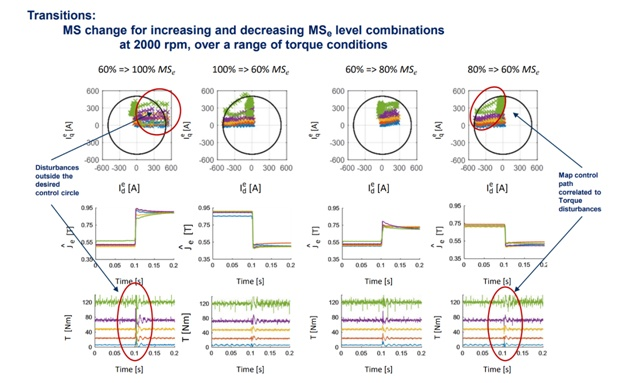
Figure 5. Effect of a periodic current pulses (control techniques) on torque output. Image Credit: Hottinger Baldwin Messtechnik GmbH (HBM)
This last example is a control problem. This was done in a special machine where amount of ID current could be pulsed at a rotor to change the magnetization state. This magnetization state basically says the magnet is going from 60% its maximum strength to 100% its maximum strength.
By pulsing a discrete amount of current at this rotor, the current response can be examined. The current goes out, up, over and back to the start. This is in the DQ plane. These currents should not exceed this black desired control circle, as this could mean demagnetization, too high a temperature, or too much torque disturbance.
When the signal is pulsed, torque can be followed. There are different loading states for the different colors, and when the DX’s current is pulsed, there is an aperiodic disturbance in torque. By using aperiodic control techniques, correlation between DQ currents and torque can be identified.
This can be used to compare torque disturbance and current disturbance. Torque disturbance could be a result of noise, vibration, or it could just be a result of efficiency. Looking at these factors, by correlating current and torque in a high bandwidth and resolution, can make connections allowing the understanding of both continuous frequency domain type things and discreet pulsation type things.

This information has been sourced, reviewed and adapted from materials provided by Hottinger Baldwin Messtechnik GmbH (HBM).
For more information on this source, please visit Hottinger Baldwin Messtechnik GmbH (HBM).